|
There are currently no product reviews.
 ;
One address for rare manuals.Very good copy. Thank you.
Your
Klaus Husse
;
All ok. I pay 5 $ and now i have 92 pages of good scaned service manual for my oooooold akai. Now i will try to repair it.
;
good and ok, very nice , good and ok, very nice, good and ok, very nice
;
Super manual it contains all the things you need to service your Marantz 2100.
;
A very easy to understand and use manual. Well worth the money.
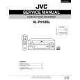
Model 204B
Section V Paragraphs 5-10 to 5-15
Figure 5-3. Cover Removal
5-10. REPAIR.
e. Remove bottom cover screw and lift tilt stand.
f . Slide bottom cover t o r e a r and lift t o remove.
5-11. When repairing the Model 204B, use the exploded view, figure5-4, as an aid t o identifying p a r t s . 5-12. COVER REMOVAL. 5-13. Remove covers prior t o any check or adjustment which requires power t o be applied. Refer t o figure 5-3, and proceed as follows:
g. Remove side cover screws and side covers. h. To replace covers and foot assembly, reverse the order of steps a through g.
5-14. SERVICING ETCHED CIRCUIT BOARDS. 5-15. The etched circuit boards used in the Model 204B require that the soldering iron tip be applied to the conductor side of the board when servicing. For large components, such as potentiometers, rotate the soldering iron tip from lead to lead while applying p r e s s u r e to the part to lift it from the board o r use a soldering tip such as Ungar #855 3/4 in. Cup Tip. In addition to the above information, the following should be observed. 5-3
a. Remove top cover screw.
b . Slide top cover t o r e a r , and lift t o remove. c. Slide r e a r foot assembly toward side while pushing foot release. d. Lift foot assembly to remove.
01369-2
|